Primary Coil:
There's not a lot you can say about my primary coil. Basically, it's a coil of copper pipe, wound in a flat pancake spiral. The diameter of the inner-most turn is 2 inches greater than the diameter of the secondary coil, and it spirals out keeping a 1/4 inch gap between adjacent turns. The total number of turns required depends on the values of the other circuit components, but a maximun of 15 turns would be a good number.
Copper tubing, normally used for central heating systems, is ideal for making primary coils. It has a large, smooth, surface area which is ideal for high frequency/high voltage use and it's easy to bend by hand.
![[copper tubing]](graphics/pipe_8mm.jpg)
A good material for mounting high voltage components on is high density polyethylene, and it's easy to get hold of in the form of a common kitchen item (see below). This is what I will be using to support the tubing. If you use wood, it should be dried out and sealed with varnish to ensure it acts as an insulator.
![[cutting board]](graphics/cutting_board.jpg)
Construction:
The first step was to unwind the copper pipe into the required spiral form. As a guide, I marked out a spiral on the base board using a pen tied to a peg with some enameled copper wire. I allowed the wire to wrap itself around the peg, effectively shortening its length 16mm for every revolution (the peg was 5mm in diameter).
With the aid of soft cotton gloves I carefully smoothed the pipe into shape. Do not straighten the tubing before starting the spiral. Keep it in its original coil (see top picture) and, starting at the centre, work it into shape. You do not need to be exact in the initial forming of the spiral but once you have it flat you can then go round making small adjustments. Keep cool and don't rush!
![[coil - unsupported]](graphics/primary1.jpg)
Cut the board into strips with a hack saw.
![[coil supports]](graphics/primary2.jpg)
Next, drill the strips (I made a little jig to help with the drilling).
![[drilled supports]](graphics/primary3.jpg)
Get yourself a cup of tea, turn on the TV and settle down to threading the supports onto your carefully formed coil. I found that the diameter of each turn increased by approx. 1/4 inch during the threading process. The roll of pipe I bought was 10m in length, giving me 9 and a bit turns (ID of 8" to clear 6" secondary).
![[primary coil]](graphics/primary4.jpg)
Connections:
There are two electrical connections to be made to the primary coil; a fixed connection at one end of the coil and a movable tapping point, to connect to any point on the coil. This is what enables us to tune the frequency of the primary tank circuit to match the natural resonance of the secondary circuit.
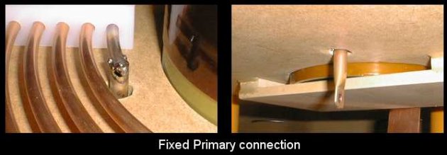
I used a short piece of 10mm copper pipe soldered to the inner turn end to make the fixed connection. We make this fixed connection to the inner turn because one of the parameters of a Tesla coil is the coupling, or distance, between the two coils. When we change the number of primary turns tapped, to alter the frequency, we do not what to change the coupling as well (coupling is adjusted by changing the height of the secondary).
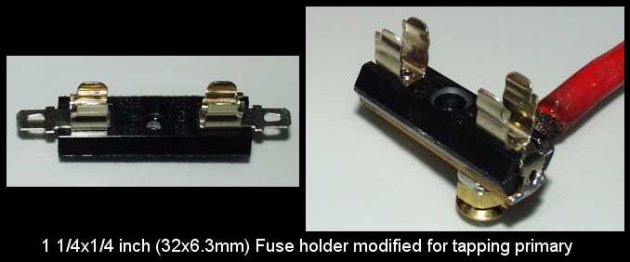
The moveable primary tap connection was made from a fuse holder. It was designed to take 6.3mm diameter fuses but with a bit of careful bending with pliers, a good connection to 8mm copper pipe is possible.
Strike Rail:
After running the coil a few times
I started to have problems with the streamers curving downwards
and striking the primary coil (see the 'Gallery' for pictures).
After only a few seconds of this behaviour, the NST died!
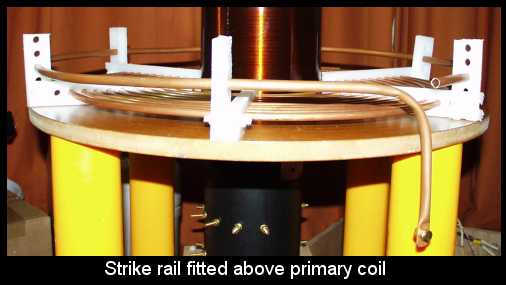
I fitted a strike rail to help protect the primary circuit components from any more damage. It consists of little more than a wire ring, positioned just above the outer edge of the primary coil, with one of its ends connected to the RF ground. It should never be made into a complete ring as this will steal large amounts of energy from the system and reduce your output. Leave one end unconnected and bring the other one down for connection to ground.
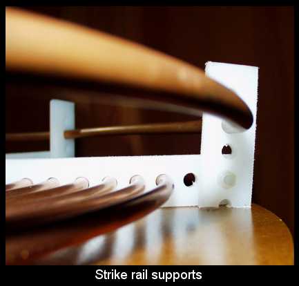
I was in a bit of a hurry with making my strike rail and had to go with what materials I had lying around. The rail itself is made of 10mm copper tubing (available from DIY plumbing stores) and you might recognise the supports already. They are, in fact, the ends of the primary coil which I trimmed off to remove the overhang! The last detail is to use some nylon nuts & bolts to join it together.
Primary Coil:
There's not a lot you can say about my primary coil. Basically, it's a coil of copper pipe, wound in a flat pancake spiral. The diameter of the inner-most turn is 2 inches greater than the diameter of the secondary coil, and it spirals out keeping a 1/4 inch gap between adjacent turns. The total number of turns required depends on the values of the other circuit components, but a maximun of 15 turns would be a good number.
Construction:
The first step was to unwind the copper pipe into the required spiral form. As a guide, I marked out a spiral on the base board using a pen tied to a peg with some enameled copper wire. I allowed the wire to wrap itself around the peg, effectively shortening its length 16mm for every revolution (the peg was 5mm in diameter).
Connections:
There are two electrical connections to be made to the primary coil; a fixed connection at one end of the coil and a movable tapping point, to connect to any point on the coil. This is what enables us to tune the frequency of the primary tank circuit to match the natural resonance of the secondary circuit.
I used a short piece of 10mm copper pipe soldered to the inner turn end to make the fixed connection. We make this fixed connection to the inner turn because one of the parameters of a Tesla coil is the coupling, or distance, between the two coils. When we change the number of primary turns tapped, to alter the frequency, we do not what to change the coupling as well (coupling is adjusted by changing the height of the secondary).
The moveable primary tap connection was made from a fuse holder. It was designed to take 6.3mm diameter fuses but with a bit of careful bending with pliers, a good connection to 8mm copper pipe is possible.
Strike Rail:
Strike Rail:
After running the coil a few times I started to have problems with the streamers curving downwards and striking the primary coil (see the 'Gallery' for pictures). After only a few seconds of this behaviour, the NST died!
I fitted a strike rail to help protect the primary circuit components from any more damage. It consists of little more than a wire ring, positioned just above the outer edge of the primary coil, with one of its ends connected to the RF ground. It should never be made into a complete ring as this will steal large amounts of energy from the system and reduce your output. Leave one end unconnected and bring the other one down for connection to ground.
I was in a bit of a hurry with making my strike rail and had to go with what materials I had lying around. The rail itself is made of 10mm copper tubing (available from DIY plumbing stores) and you might recognise the supports already. They are, in fact, the ends of the primary coil which I trimmed off to remove the overhang! The last detail is to use some nylon nuts & bolts to join it together.