-
 P
= input power in watts
P
= input power in watts
- L = spark length in inches
- Example: For 50 inches of spark, the power required is 865 watts
What
is a Tesla Coil?
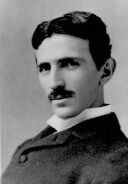 The
'Tesla Coil' is a device invented by the brilliant scientist Nikola
Tesla (born 1856, died1943). It is a high voltage, high frequency,
power generator, primarily built for conducting experiments and
to observe phenomenon associated with alternating electricity.
With this coil, Tesla was able to generate voltages of such magnitude,
they would shoot out of the apparatus as bolts of lightning!
The
'Tesla Coil' is a device invented by the brilliant scientist Nikola
Tesla (born 1856, died1943). It is a high voltage, high frequency,
power generator, primarily built for conducting experiments and
to observe phenomenon associated with alternating electricity.
With this coil, Tesla was able to generate voltages of such magnitude,
they would shoot out of the apparatus as bolts of lightning!
Although
the sight of writhing streamers of electricity jumping though
the air is certainly spectacular, to Tesla it represented energy
loss. On occasion, Tesla deliberately adjusted his equipment to
produce these visible outputs as a means of gauging the state
of tune of the system, and to provide some feedback for his experimentations.
Today,
Tesla Coils are built by amateurs all over the world for one reason
only, the thrill of making your very own Lightning!
So
you want to build a Tesla Coil!
 Step
1 - Motivation
Step
1 - Motivation
Initially,
your sole reason for wanting to build a Tesla Coil is to see the
fantastic light show they produce. You've surfed the Internet
and seen that it's possible for anyone to build a coil, so you're
thinking that you want to give it a try.

Required
skills: Building a coil requires ability in many different areas
of engineering. You will need to work with wood, metal, plastics,
adhesives/sealants; use hand and power tools for cutting and drilling;
work with mains electricity, wiring, soldering; improvise and modify
stock items, perform simple mathematical calculations, plan your
coil around what components you can find/afford. And finally, the
most important requirement of all is Time! Lots of it!
Step
2 - Size Matters
Most
of what you will now read here will seem dull and far away from
the excitment of homemade lightning. You'll probably want to skip
it and start building straight away but if you do you will soon
find yourself with lots of questions and no answers. You really
do need a plan!
What
size coil are you going to build? If money is no object, you
can get hold of all the components you need for your coil, from
anywhere in the world, and build a really powerfull one, but there's
a little more to it than that.
How
big should your coil be? When I talk about size I could be referring
to the physical dimensions of the coil, how tall and wide it is,
or I could be talking about the power rating, how many watts of
electricity it will consume. You are probably initially only thinking
about the size of the sparks you want to produce, so as a rough
guide you can use the following equation to calculate an input
power figure for an approximate spark length:
Before
you get carried away, there is one rather important point you should
consider:-
Do
you have the space to power up your coil?

Here
in the UK, an average sized single garage has sufficient room for
a Tesla Coil around the 1kW power level. The output streamers will
be cut short by the walls and ceiling but not too much.
 You
may be tempted to build a really big coil and run lt outdoors.
It would be much more impressive and more people could watch it
at the same time, without having to crowd into a small garage,
but be warned! Pictures on a web site do not convey the real impact
a coil makes.
You
may be tempted to build a really big coil and run lt outdoors.
It would be much more impressive and more people could watch it
at the same time, without having to crowd into a small garage,
but be warned! Pictures on a web site do not convey the real impact
a coil makes.
Tesla
Coils are VERY VERY LOUD!!!
Don't
build a coil capable of 7 foot long sparks and run it in the garden,
only to find the neighbours get upset and call the Police!
Step
3 - Finding the Parts
Power
Transformer:
The
hardest component to get is the power transformer, and the range
of available High Voltage transformers is small. A
suitable voltage is from 6kV to 15kV(RMS).
Neon
Sign Transformer
Pole
Pig
20 KG
200KG !!
The
ultimate transformer is a 'Pole Pig' but it is not easy to get
one, and there are problems associated with transportation! For
the average person, the only possibilities are OBITs (Oil-fired
Boiler Ignition Transformers) and NSTs.
Check
out your local (and national) telephone directory for businesses
that deal in oil fired central heating or neon signs.
You
may have decided on the size of spark you want but the real limit
to your output is the transformer you manage to find.
Secondary
Coil Wire:
It
is recommended that you wind the secondary coil with one continuous
piece of wire. Small quantities of enameled copper wire are readily
available from hobbyist electronic component shops and mail-order
firms. Reel sizes vary from 50 grams to 500 grams, which is fine
for small coils but you will not have enough to make a medium
sized one.
You
will need to find a local company that will either sell you wire
in the quanties you need or who know of a supplier that will (wire
tends to come on 20Kg reels!).
Capacitors:
The
recommend type of capacitor for the tank circuit is currently
the MMC (multi-mini-cap). It is easy to build, easy to transport,
relatively cheap to make and is an excellent performer.
The
individual capacitors that make up the MMC (and the associated
bleed resistors) are available from mail-order electronics companies.
The
Rest:
All
the other material are readily available from local DIY stores.
Step
3 - Design
You
should start calculating the design parameters based on the power
rating of the transformer you are using.
Example:
If you had an NST rated at 10KVRMS@60mA then the power is
V x I = 10000 x 0.060 = 600Watts.

Secondary
Coil:
The
power rating of a coil relates directly to the size of the secondary
because as the spark length increases with power, you get damaging
strikes to the primary coil unless you make the secondary coil
taller.
(You
can add a strike rail to the primary coil to protect it but if
your secondary is just too short for the power rating then all
you will get is strike rail hits and few streamers into the air).
What is a Tesla Coil?
Although the sight of writhing streamers of electricity jumping though the air is certainly spectacular, to Tesla it represented energy loss. On occasion, Tesla deliberately adjusted his equipment to produce these visible outputs as a means of gauging the state of tune of the system, and to provide some feedback for his experimentations. Today, Tesla Coils are built by amateurs all over the world for one reason only, the thrill of making your very own Lightning! |
||||||||
|
|
||||||||
So you want to build a Tesla Coil!
Initially, your sole reason for wanting to build a Tesla Coil is to see the fantastic light show they produce. You've surfed the Internet and seen that it's possible for anyone to build a coil, so you're thinking that you want to give it a try. |
|
|||||||
|
Required skills: Building a coil requires ability in many different areas of engineering. You will need to work with wood, metal, plastics, adhesives/sealants; use hand and power tools for cutting and drilling; work with mains electricity, wiring, soldering; improvise and modify stock items, perform simple mathematical calculations, plan your coil around what components you can find/afford. And finally, the most important requirement of all is Time! Lots of it! | |||||||
Most of what you will now read here will seem dull and far away from the excitment of homemade lightning. You'll probably want to skip it and start building straight away but if you do you will soon find yourself with lots of questions and no answers. You really do need a plan! What size coil are you going to build? If money is no object, you can get hold of all the components you need for your coil, from anywhere in the world, and build a really powerfull one, but there's a little more to it than that. How big should your coil be? When I talk about size I could be referring to the physical dimensions of the coil, how tall and wide it is, or I could be talking about the power rating, how many watts of electricity it will consume. You are probably initially only thinking about the size of the sparks you want to produce, so as a rough guide you can use the following equation to calculate an input power figure for an approximate spark length: |
||||||||
|
||||||||
| Before
you get carried away, there is one rather important point you should
consider:-
Do you have the space to power up your coil? |
|
|||||||
| Here
in the UK, an average sized single garage has sufficient room for
a Tesla Coil around the 1kW power level. The output streamers will
be cut short by the walls and ceiling but not too much.
Tesla Coils are VERY VERY LOUD!!! |
||||||||
| Don't build a coil capable of 7 foot long sparks and run it in the garden, only to find the neighbours get upset and call the Police! | ||||||||
Power
Transformer:
|
||||||||
|
|
|
|
|
|
|
|
The ultimate transformer is a 'Pole Pig' but it is not easy to get one, and there are problems associated with transportation! For the average person, the only possibilities are OBITs (Oil-fired Boiler Ignition Transformers) and NSTs.
Check out your local (and national) telephone directory for businesses that deal in oil fired central heating or neon signs.
You may have decided on the size of spark you want but the real limit to your output is the transformer you manage to find.
Secondary
Coil Wire:
It
is recommended that you wind the secondary coil with one continuous
piece of wire. Small quantities of enameled copper wire are readily
available from hobbyist electronic component shops and mail-order
firms. Reel sizes vary from 50 grams to 500 grams, which is fine
for small coils but you will not have enough to make a medium
sized one.
You will need to find a local company that will either sell you wire in the quanties you need or who know of a supplier that will (wire tends to come on 20Kg reels!).
Capacitors:
The
recommend type of capacitor for the tank circuit is currently
the MMC (multi-mini-cap). It is easy to build, easy to transport,
relatively cheap to make and is an excellent performer.
The individual capacitors that make up the MMC (and the associated bleed resistors) are available from mail-order electronics companies.
The
Rest:
All
the other material are readily available from local DIY stores.
Example:
If you had an NST rated at 10KVRMS@60mA then the power is
V x I = 10000 x 0.060 = 600Watts.
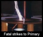
The power rating of a coil relates directly to the size of the secondary because as the spark length increases with power, you get damaging strikes to the primary coil unless you make the secondary coil taller.
(You can add a strike rail to the primary coil to protect it but if your secondary is just too short for the power rating then all you will get is strike rail hits and few streamers into the air).
Use this table as a rough guide to choosing the diameter of your secondary coil form.
Power Range
Secondary Diameter
less than 500W
500W to 1500W
1500W to 3KW
3KW and above
After lots of experimentation, the modern pioneers of Tesla Coiling have come up with the following rules for determining the optimum size of a secondary coil (see table). This gives you size of coil, so to get the form length add a couple of inches to the coil length.
3 inches
4 inches
6 inches
8 inches and above
Enameled
copper wire comes in a wide range of diameters. You are aiming to have
around 800 to 1000 turns of wire for your secondary coil so divide the
coil length just worked out by say 900, to get the approximate wire
thickness. The values manufacturers quote are for the copper conductor
diameter. The enamel insulation usually makes the wire approx 10% thicker
so allow for this in your sums.
Electrical Values:
Example: For the 4 to 6 inch coil form range, if you choose 4 inch then the height of the wound coil will be 5 x 4 = 20 inches. Add a couple of inches to the length to get the actual length of plastic tube you need to get.
Wire:

Example: Your chosen coil length is 20 inches, or 508mm.
508 divided by 900 = 0.564mm per wind.
Taking into account an approx. 10% increase for enamel,
wire (conductor) diameter = 0.564mm / 1.1 = 0.51mm.
You may not be able to get 0.51mm diameter wire so find the nearest available size and check out how many turns it works out to.
The coil has a characteristic inductance and capacitance which you will
need to know. Feed the dimensions of your coil into the 'Helical Coil'
calculator (see the 'Equations'
section), using the 10% enamel width value for the turn spacing value.
Example:
A 152mm diameter coil, wound with 825 turns of 0.71mm wire (10%
of 0.71mm gives a 0.071mm spacing), has values of
L = 21.7mH (21716uH) & C = 10.45pF
with a wind height of 644mm.
 Discharge Terminal: Discharge Terminal: |
|||
|
Now that the dimensions of the secondary coil have been determined you should think about the top load, or discharge terminal.
The classic shape is the torus (ring doughnut shape) but anything without sharp corners will work. The obvious alternative is a sphere. Electrical Value: Calculate the capacitance of the top load and together with the calculated inductance (and self-capacitance) of the secondary, you can work out the resonant frequency for the secondary circuit (see below).
|
|||
|
|
||
Resonant Frequency of Secondary Circuit |
 |
|
| We now have the two parameters needed to calculate the resonant frequency of the secondary circuit, namely the secondary inductance and the combined top-load and secondary capacitance.
Use the 'LC Calculator' to work out this frequency. |
||
|
||
A capacitor which is smaller or larger than this value will still work but the power output will be less. Smaller is better than larger because it's cheaper! Use the 'Cap Calculator' to find the matched value of capacitance for your transformer.
If you decide on building an MMC style cap, use the 'MMC Calculator' to work out the number of individual components you will need.
Using the 'LC Calculator' again, we feed in the value of our primary tank capacitor and then experiment with different values for L until we get a frequency match to the secondary circuit. With a value of L = 0.03mH we get a res freq of 165KHz, which is too low, and with L = 0.01, F = 286KHz, too high.
With
D1 = 8 inches, W = 0.315 inches, S = 0.315 inches & N =
10 By trying a few different numbers for N, we eventually find that 7 turns gives us a value L = 0.019221mH (19.221uH) which is close enough to our target. To allow for variations in component value and for experimentation, increase the number of primary turns by about 50% (7 turns goes up to about 10).
The type of material and the size of the electrodes will affect the time the coil can be run before the gap gets too hot and vapourises itself. Copper requires regular cleaning to maintain maximum performance whereas tungsten would not. Cooling can be added to help, in the form of a fan or blower. Vacuum cleaners are a favourite choice for coilers.
 Primary Tank Capacitor:
For maximum output from your coil the value of the tank capacitor can be calculated to match the transformer you are using. The spark gap fires and transfers energy from the tank cap to the primary coil every half-cycle of the mains supply (e.g. 100 times a second for 50Hz supply). This means that the transformer only has the time in one half-cycle (10mS) to recharge the capacitor for the next firing of the gap. A capacitor that is only charged up to half its capacity in the time allowed is not being used fully, and a small cap which could be charged twice over in the time is missing out on half the power available.
Example: A 10KV(50Hz) 100mA NST can run at maximum effieiency with a 0.031uF cap.
 Primary Coil:
The primary coil and the main tank capacitor form the primary resonant (LC) circuit. For proper operation, a Tesla Coil must have identical primary and secondary resonant frequencies.
Example: Using the value of 0.031uF for our primary cap, we will aim to match the resonant frequency of 207KHz (secondary circuit) by trying different values for 'L' in the 'LC Calculator'.
With a little playing we find that we get a good match with
L = 0.019mH.
Having calculated the required inductance, you now need to decide on the actual physical parameters of the primary coil.
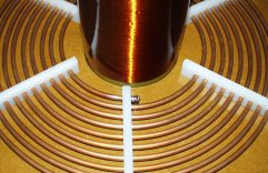
For a flat spiral coil, which is the prefered choice, you need to know the width and spacing of the conductor, the diameter of the inner turn and the number of turns to be able to find its inductance value. Use the 'Spiral Coil Calculator' to find a match for your target inductance.
Example:
We are aiming for a value of 0.019mH for our primary coil. The
diameter of its inner-most turn needs to be a couple of inches
larger than the secondary coil diameter, so for a 6 inch secondary
we get a value of 8 inches (1 inch clearance all round). We'll
choose to use 8mm (0.315 inch) copper pipe for the conductor,
with a gap of 8mm (0.315 inch) between each turn.
we get a value of L = 40.413uH (or 0.040413mH).
 Spark Gap:
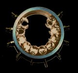
The Spark Gap is the power switch for the primary tank circuit. It uses the air to conduct electricity between its electrodes and generates a great deal of heat in the process.
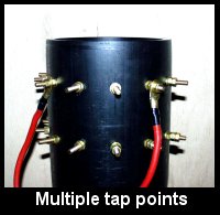
The size of the total gap is dependant on the supply, the higher the voltage the larger the gap that can be used. The gap is usually split into lots of smaller gaps, all wired together in series. This is done for two reasons; 1) The more gaps you have the more power it can handle; 2) It is possible to vary the firing voltage of the gap by changing the number of electrodes that are in circuit (by moving the connecting wires).
Individual gap spacing of 20 to 30 thou (thousandth of an inch), 0.5 to 0.75mm, with the total gap being around 6mm for a 10kV supply is roughly the sort of dimensions you need, but it's not critical. If the total gap is too big then the supply will not be able to break down the air and fire the gap properly, and if it is too small then it will still work but at less than optimum performance.