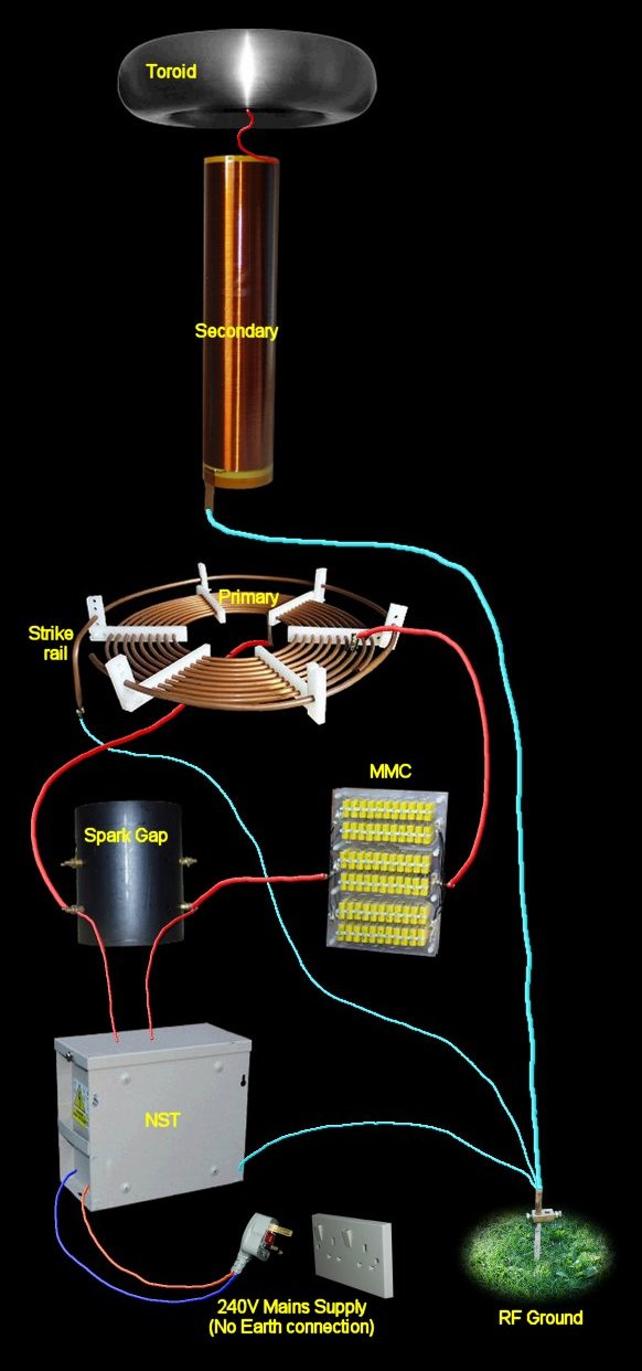
Wire
Types and Sizes
The
type and size of wire used in a Tesla Coil system should be chosen to
match the specific needs of each part of the circuit. The system can
be split into four sections:
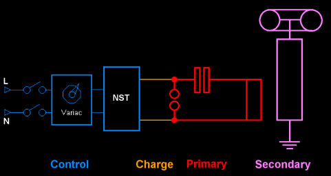
The
Control section uses correctly rated mains cable.
Typical cables are 'E' & 'D' (see below).
The
Charge section is high voltage and low current.
Suitable cables are 'A' & 'B'.
The
Primary section is high voltage and high current.
Suitable cable is 'F'.
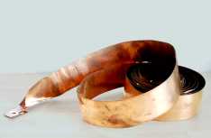
The
Secondary section. The RF ground connection is low voltage
and high current.
Suitable cable is 'F'.
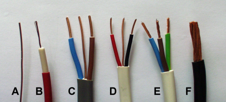
| A |
bare
single strand (1.0 sq mm) |
| B |
EHT
cable 25KVDC |
| C |
twin
and earth (2.5 sq mm) |
| D |
twin
and earth (1.0 sq mm) |
| E |
3
core flex 16A (1.5 sq mm) |
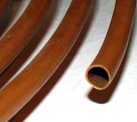
| F |
car
battery lead (overall diameter 8mm) |
Voltage:
Because
of the high voltages found in a Charge & Primary sections
it seems natural to look for cable with high voltage ratings, such as
neon sign cable, medical X-ray equipment cable & car engine spark
plug leads. The first two would be fine for connecting the NST to the
spark gap but the spark plug leads are useless (too high a resistance).
However, you don't need to spend lots of money on fancy HV cable because
all sorts of ordinary wire would work too. All you need to do is think
about insulation.
Insulation:
For
a circuit to work you need wires to conduct the electricity between
the components. A bare piece of wire will do this perfectly but you
now have the problem of wires accidentally touching and shorting out.
Depending on the voltage being used you may also have the added risk
of electrocution! Insulation is used to solve both these problems but
for high voltages, like in a Tesla Coil, the cost of suitably insulated
cable is high.
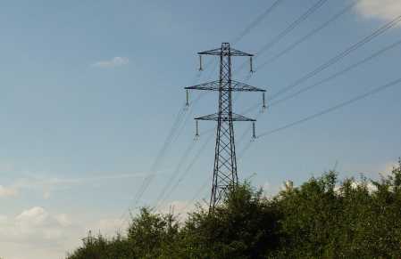
The
solution is to use ordinary low voltage cable, or bare wire, and use
air as your insulatior (just like the big boys do with the National
Power Grid!). All you need to do is to secure the wires in such a way
that they cannot short against anything conductive and are at a safe
distance from operator's hands.
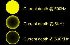
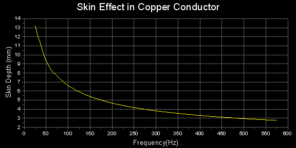
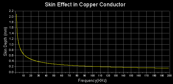
Current:
All
conductors, except for 'superconductors', resist the flow of current
through them. The value of this resistance is determined by the material
used for the conductor and by its size.
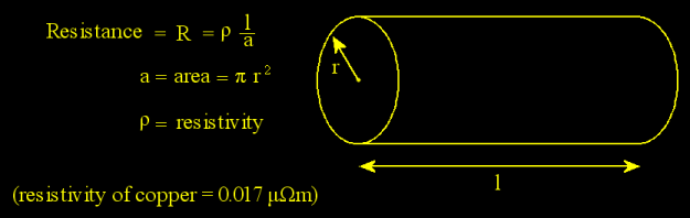
As the cross-sectional area 'a'
gets smaller, or the length of the wire 'l'
gets longer, the resistance 'R'
increases.The higher the resistance the more electrical energy is used
just in fighting against it. This causes power to be lost in the form
of heat.

- Example:
The
heating element in an electric kettle uses wire with a high
resistance to generate heat. The wire connecting the kettle
to the wall socket has a very low resistance, to avoid
heating.
|
High
current:
High current connections in the 'Primary' section
require thick cables to keep resistance values to a minimum. Cables
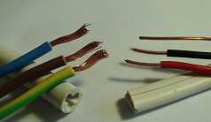
'C', 'D' and 'E' can be used for high current Tesla
Coil use but should be treated as single conductors (see below). Cable
'F' is good for high currents too but not as easy to find in
the shops.
|
Conductors
joined together at both ends for high current use
|
|
Low
Current:
The low current 'Charge' section can use thin cable without any
measurable loss of power. Cables 'A' and 'B' are fine.
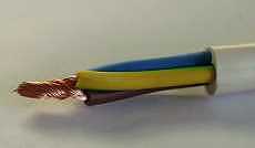
By removing the outermost layer of insulation from cables 'C',
'D' and 'E' the individual wires are perfect too (see
below).
|
|
Conductors
separated for low current use
|